Architecture
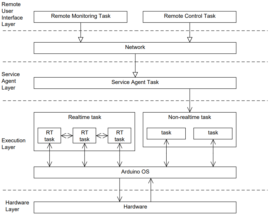
Initial Drone architecture will be using a Service containing N acyclic tasks to be triggered, all data signals will travel via the Service Agent layer to and from the UAV and the Ground Station.

Real time tasks will cross communicate but no acyclic task will communicate with a real time task. Services will be received via the Interface Rx component and decompiled into there corresponding tasks to be executed by the Interface Rx component. All data signals will be transmitted by the Interface Tx component.
Hardware
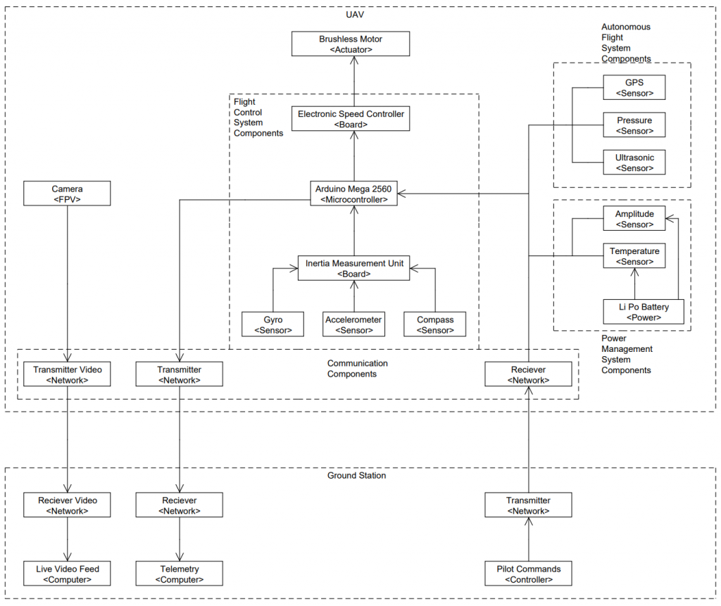
Initial design is separated into UAV and Ground Station Systems. The UAV System features five distinct hardware sub-systems:
- Flight Control
- Autonomous Flight
- Power Management
- Communication
- Camera (First Person View)

The Camera (FPV) System will not be connected to the Arduino Mega 2560 Microcontroller and has a dedicated transmission interface, therefore this system requires no software development and no software solution will be designed.
Software
Initial Software Design contains eighteen system components:
- General Systems
- System Mode – Manage System Mode of software (Standby, Manual, Automatic)
- Flight Control System
- IMU – Interface to IMU chipset
- Motor – Interface to Motors
- PID – Calculate error from data read from IMU component
- Flight Control System – Manage Aerodynamic Profile and append with data from PID component and control Motor Speeds
- PWM Convertor – Convert calculated aerodynamic profile into power commands for the motors.
- Communication
- Interface Rx – Recieve external data signals sent by Pilot / Operator (Manual, Automatic, Flight Plan, X, Y, Z Orientation, Activate Automated Flight)
- Interface Tx – Transmit data signals to Ground Station (Telemetry XYZ, Abort Flight Message, Power Status Message, GPS Position)
- Automated Flight System
- Automated Flight System – Manage all Automated Sub Systems
- Route Guidance – Manage a list of Points to be flown in an automated Route, detect capture of points and calculate aerodynamic profile to travel between points
- Flight Plan – Stores all points to be flown in automated Route
- GPS – Interface to Global Positioning System
- Feasibility – Reads Wind Speed, Remaining Power, Present Position of Drone and calculates the feasibility of flight – aborts flight if not feasible.
- Pressure – Interface to Wind Pressure Sensor
- Obstacle Awareness System – Reads Ultrasonic Sensor data and compares data against Safety proximity profile, when profile exceeded obstacle is detected, a new point is calculated in the automated route and the drone flies to the new point to avoid the obstacle.
- Ultrasonic – Interface to Ultrasonic Sensors
- Power Management System
- Power Management – Reads Battery Amplitude and aborts flight if amplitude is too low
- Amplitude Sensor – Interface to Amplitude Sensor

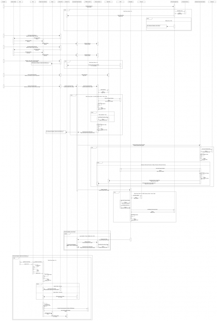
Identified in the Software Design process are six real time cyclic tasks and six acyclic tasks:
- Acyclic Task
- Set System Mode Manual
- Set System Mode Automatic
- Upload Flight Plan
- Activate Automated Flight
- Set Roll, Pitch, Yaw, Thrust Aerodynamic Profile
- Abort Flight
- Cyclic Realtime Task
- Power Management
- GPS
- Route Guidance
- Feasability
- Obstacle Awareness
- Flight Control Behaviour